 |
This page tells of my Canon camera modification to allow electronic shutter control and of my repair attempts after the camera suddenly failed with an E18 error problem. See SABLE for information about the high altitude balloon photography flight |
Canon PowerShot S200 Digital IXUS V2
|
|
|
The camera can be set through it's menu for everything required, like never powering off, and the shutter only needs to be controlled which should be easy to do by simply bridging the two stage shutter push button with two transistor switches controlled by either a PIC micro processor or even a simple timer chip. First thing was to disassemble the camera to check the shutter switch and see if my plan would work and to find room for a small jack to make control circuit connection easy and to allow normal camera use at other times. Most cameras have no extra space, but many use the LCD display as a viewfinder so the optical viewfinder is often a perfect space for "extras" like a jack. |
 |
|
|
|
|
|
|
+3.7V |
|
|
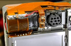
A 8 pin mini-DIN jack was machined to fit in the viewfinder assembly and #30AWG stranded wires were added. The jack was then installed in the viewfinder assembly using 5 minute epoxy and with assembly back in the camera, two of the jacks wires were connected as shown, which are fused connections directly from the camera's battery. |
|||

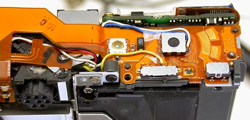 |
Three of the other jack conductors were then connected to the shutter switch. |
|
|
With the switch housing in place, there is little space for additional wiring under it and even small #30 conductors must be routed as shown. Tape helps to keep the wires in place while installing the housing.
Do not forget the insulating tape over the camera battery supply connections and when reassembled, except for the case front & rear halves, the camera can be tested for proper operation. |
|
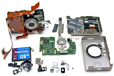
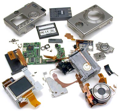
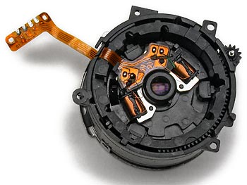
A few final notes...... The first photo of the disassembled camera shows the camera's circuit board removed, but this is not required to do what was shown here. I simply didn't have a more appropriate photo and, in this case, the board was removed in order to examine and determine where various connections went in order to determine the best way to do things. A 5 pin mini-DIN jack would have worked just as well as the 8 pin one as they are all the same physical size, but the 3 extra pins gave me the option to monitor or control 3 additional camera points later for whatever may come up. |
|
Then the fun began ........ ........ if you can call it fun! To remove the camera lens assembly the camera must be disassembled further then it was to add the mini jack. But why, you ask, would anyone want to remove the lens assembly? Because........... Shortly after operating the camera to measure the switch contact voltages needed to design the shutter control circuit the camera decided to fail & display the famous Canon E18 Error Message on it's LCD display. If you have not heard of the Canon E18 error message, do a Google search on Canon E18 Error and check some of the 26,000 pages found, or simply check the following pages which are as good as any. |
|
|
http://www.e18error.com/repair.html Most E18 problems appear to be mechanical and due to dirt or the camera being dropped, but I agree with those that feel this problem is more serious and that Canon cameras have a design flaw. Why else do some have the error appear and the camera shut down for no reason after working fine moments before? Or see the problem disappear after connecting the camera to a TV with an A/V cable, after reformatting or swapping the memory card, after turning the camera off & on again or after the camera has been off for a period of time. Another quick fix that appears to work is to tap the USB connector end of the camera on a hard surface, but whether these tricks free a stuck lens or point to a more serious problem like software, soldering, or intermittent connectors/components is anyone's guess with Canon refusing to help and blaming this problem, almost always, on user abuse. This camera's lens assemble could not operate more smoothly, the camera has never been abused and it is an example of one that developed an E18 error for no obvious reason. The prove there was no mechanical problem, the lens assembly was removed and the motor was operated on reduced voltage. Any smooth operation problem will affect the motor's load and now cause a noticeable change in motor speed, but the motor repeatedly extended and retracted the lens slowly without a problem. When this camera is turned on the lens fully extends. Then, after a briefly delay, the camera tries to extend the lens even further, which is not possible, so the motor stalls and I assume this is what is detected as an E18 error. The internal lens shutter never operates during any of this so I have to wonder if this may be part of the problem also. With no light thru the lens, was the camera attempting to extend the lens and open the external lens shutter again? To test this theory, I opened the internal lens shutter and tried the camera again. I hoped to at least see something different happen, like the internal lens shutter close, but everything operated exactly the same as before. Does the camera not check, or care about, the state of the internal or external lens shutters? Rather then trying to extend the lens a second time, was the camera perhaps trying to auto focus? Had the CCD failed? One can only guess what is happening with Canon refusing to answer questions or provide service information which makes me extremely mad as this could be a very simple problem to solve if one had even a little technical information. After spending several days to install the mini-DIN jack, nearly a month has been spent trying to get it to work again. But enough time has been wasted and it is time to find something better to use, without a history of problems and perhaps one with a Fujitsu chipset to allow control of the camera through a serial interface. For further information on what was found and used for the balloon photo mission, check the SABLE web page. |
|
Following is what I found out, or assume to be true, about the camera lens assembly. (A lot has to be assumed with Canon being so damn secretive about their products) |
|
 |
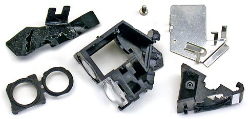
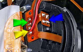
Lens Assembly Front Half ....... The front half of the lens assembly contains two actuators. |
|
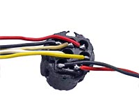
Green Arrow points to neutral density filter coil connections. To the upper of the coil connections Yellow Arrow points to shutter coil connections. Blue Arrow - See blue arrow below for further description. |
|
|
|
|
|
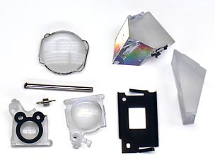
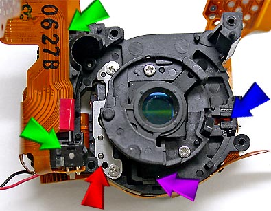
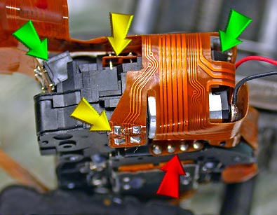
Blue Arrow points to a photo-interrupter slot for detecting when the front lens is fully retracted. Red Arrow points to a metal plate and connections to two coils of a stepper type motor under the plate that adjusts the CCD to rear lens distance to provide zoom capability.
Green Arrows point to two devices with 4 leads that look like photo reflective sensors, but there is nothing to sense. They are installed at an angle and I am guessing that they are the Intelligent Orientation Sensors. In the photos, one or the other is usually hidden under the ribbon cable where a green arrow is pointing. A better sensor view is to the right --------------- Yellow Arrows point to 2 photo-interrupters for sensing the lens motor speed and direction of rotation. |
|
|
|
|
|
Thousands of others have already written plenty about Canon and the E18 error problem, but Canon, You Screwed Up - Why not admit it? Or why not at least provide some technical information to help some of the 10's of thousands of camera owners suffering from E18 error problems solve their camera problem themselves? Or is it true, what it appears to be, that no one at Canon gives a damn about customers, has a clue how their cameras work, and how to find or repair the real problem? Canon insists their cameras are a solid design and that they have no design flaw, but refusing to provide service information tells me the opposite is true, that Canon is trying to keep others from discovering the truth and from having to recall thousands of cameras. Good Luck Canon! In the end I hope this costs you big! As for a solid design - After many complaints Canon posted this on their web site: "The E18 error code may be displayed if you apply pressure to the zoom lens, lens barrier or surrounding area when handling the camera. Hold the camera so that your fingers do not touch the
zoom lens." Does this sound like a solid design to you? Even if this camera was a solid design, it is certainly not a good design in my opinion.
As for Canon's favorite response - "Only the Canon Factory can test the camera internally and determine the exact issue". Canon may be able to keep me from knowing much about their cameras, but there is one thing Canon could not keep me from learning, which is to - Never Buy a Canon Camera! |
|
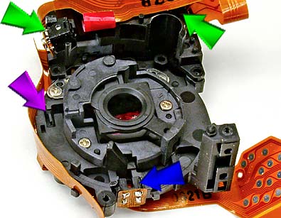
 Magenta Arrow points to a photo-interrupter slot that detects the position of the rear lens.
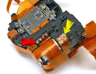
|