 |
VE6EMU 6 Meter Beacon
|
|
I had an APRS tracker to finish for SABLE-3, then help with the launch, deal with all the photo's and update the SABLE-3 website before I could even take a quick look at Barry's radio. But the aftermath of SABLE-3 then delayed things even longer and with the success of SABLE-3 came plans for another balloon flight and I quickly found myself busy trying to get things done for it hopefully in time to have the flight before winter. I also became busy helping a friend find a new home for things he had to part with when he had to move and after seeing 'What's Wrong' you'll understand why this delayed work on the beacon radio even longer. I was still busy trying to find or make space for everything hauled home from my friends place and trying to finish a number of projects that were tying up my workbench in late November when winter arrived and ended the hope of having another balloon flight, but work on the beacon radio had already been delayed far too long so I put everything else on hold, pushed the unfinished projects on the workbench aside and started work on the radio. |
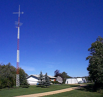
The VE6EMU 6M Beacon location, |
|
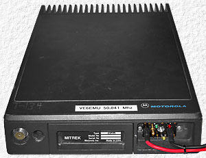
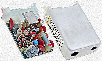
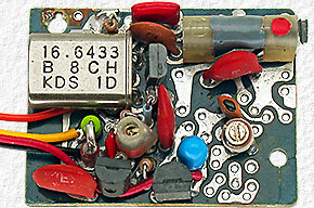
The beacon transmitter was a 100W Mitrek Mobile Radio with a PIC 16C84 on a small circuit board to generate the CW ID signal which was glued to a block of foam which in turn was glued into the radio with silicon sealant. A KXN1087 channel element with a 16.68033 MHz HC-49 style crystal is normally used in a Mitrek for 50.041 MHz, but a 16.70972 MHz larger style HC-51 crystal was used in this radio which didn't allow use of the channel element's metal enclosure. The radio's signal was reported to begin sounding strange before it quit completely which made me suspect an oscillator problem and it didn't take long to confirm this, find that a capacitor in the channel element had developed a short and replace the capacitor. |
 |
|
After a quick tune-up the radio was as good as before and this should have been the end of the story, BUT, as usual, I just couldn't leave well enough alone and had to go and try to improve a few things and and it wasn't long before I had turned Barry's radio into another whole new project that delayed getting the beacon back on the air for several more weeks. |
|
|
January 2015 I started this page as soon as the radio was eventually finished and while everything was fresh in my mind, but only made it this far before being distracted by something that got me working on another project. I've tried to get back to and finish this page ever since and now, over 7 years later, I've decided to finally finish it while taking a break from projects to do some long overdue web site maintenance as I know it may never get finished if not finished now before returning to my workshop and projects. I should have finished it much sooner as now I'm left with a folder of countless images and trying to remember exactly what I was going to write about each one, but will try my best to be as accurate as possible. |
Temperature Compensation of a KXN1088 Channel Element . . . . . .A KXN1087 channel element is normally used for 50 MHz in a Mitrek radio, but without the label from the elements missing enclosure it's hard to know whether a KXN1087 or KXN1088 channel element was used in this radio as I've never seen a KXN1087 element and the one in this radio has a circuit board identical to what's found in a KXN1088 channel element. |
||
 |
(Left) The Channel Element that (Right) |
 |
|
Without a metal enclosure the channel element was sensitive to hand capacitance which made frequency adjustment difficult. Once it was on frequency replacing the top on the radio case didn't affect the frequency, but I didn't like the situation and decided to try and make it better. I first tried grounding the metal shell of the crystal, but that made little difference so I began making an element enclosure from sheet copper until finding that the element had a more serious temperature stability problem. I then learned from Barry that the temperature at the beacon site varies about 10°C and that he's seen the frequency change at least several KHz which would be about right for a crystal with no temperature compensation. I also learned that the radio may soon have to be moved to a site with no environment control which would mean the temperature could vary from less then −30°C to over +40°C so I quite working on an enclosure and decided instead to try to improve the crystals temperature compensation. The Mitrek / MSR2000 Channel Element Page on the Repeater Builder's web site has some good element information and the Why spend the $ to re-crystal a channel element page has lots of good temperature compensation information and a page anyone planning to re-crystal an element should definitely read. The page explains why it's important to pay the extra cost to have the crystal manufacturer re-crystal elements properly and while I agree that one should do this, I never have myself and know many amateurs don't. One reason for this is that many amateurs have their equipment located where the temperature is fairly stable plus, as many know, most amateurs are very thrifty (ok, cheap). I've even occasionally used a crystal of a slightly different frequency than specified by the manufacture, like whoever used the 16.70972 MHz crystal in Barry's radio, and the first thing I did when finding the element was sensitive to hand capacitance was to check my stock of smaller salvaged HC-49 crystals for one close enough in frequency to allow the use of a regular element enclosure. |
||
 |
Right - Left - an |
 |
 |
The HC-51 crystal with the radio is 29.39 KHz higher than spec'd and a smaller HC-49 crystal 37.03 KHz lower than spec'd found in my collection of crystals was tried, but it was further from the spec'd frequency than the HC-51 plus how far one can pull the frequency of a particular crystal depends on the type of crystal and the smaller crystal couldn't be pulled far enough to be used. Left - a modified KXN1088A Channel Element with the smaller crystal that was tried. |
|
 |
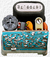
Left - When the HC49 crystal didn't work it was simply replaced with the larger HC-51 crystal. It may appear that a different KXN1088A channel element was modified and used for the HC-51 crystal, but the larger crystal simply required also changing some of the capacitors. |
|
|
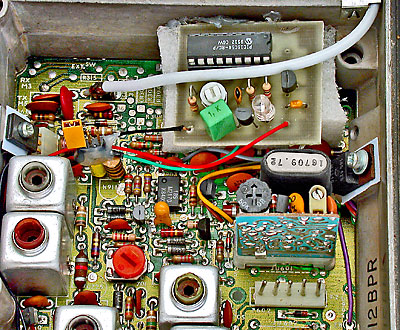
I didn't want to alter the circuit board of the channel element that was received with the radio (and I had repaired) just in case the new modified channel element I planned to make didn't work out and I needed the original board to get the radio working again. As one can see a number of paragraphs above, the channel element that came with the 6M Beacon Radio looks the same as any KXN1088A element except for having a much larger crystal. My modified board looks quite different however as (1) unused components, like those for FM modulation, were removed to make room for a voltage regulator and it easier to swap capacitors when doing temperature compensation which sometimes required using several capacitors in parallel. (2) the molded plastic that made the element a plug-in unit was removed and wire leads were added as the modified element was going to be hard wired into a larger plug-in assembly. |
||
|
I didn't realized how temperature sensitive a crystal oscillator circuit could be until trying to find the right temperature compensation capacitors to use with the crystal, but after several days of trying countless different combinations of whatever positive and negative temperature coefficient capacitor values I had on hand, I managed to get the change in transmitter frequency down to 250 Hz over the temperature range of 25 to 60°C. How did I heat the oscillator circuit? 250 Hz (5 ppm) over a 35°C (95°F) temperature range was better than I expected to achieve by trial and error, but from the start I planned to make an OCXO (Oven Controlled Crystal Oscillator) from the channel element and the frequency vs. temperature tests weren't done until after the oven was made and the oscillator circuit was in it. Why did I chose to use a 25 to 60°C temperature range? 25°C was slightly higher than my workshop temperature so a convenient starting temperature. The oven and oscillator circuit would be from 20 to 24°C when each test was started and I would simply record the frequency when the display on the digital temperature gauge being used changed from 24.9 to 25.0°C. And 60°C is a common OCXO operating temperature, the temperature determined to be best for the crystal being used and a convenient ending temperature as the oven controller would heat up and hold the oven at that temperature until I had recorded the frequency at 60°C and turned the oven off. |
||
  |
||
|
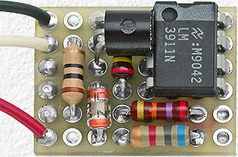
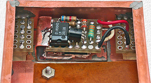
Above - The Oven Heater uses a LM3911 temperature controller I.C. and a TO-220 style LM317 voltage regulator which is installed under the circuit board and used as a 5W heating element. |
||
 |
|
|
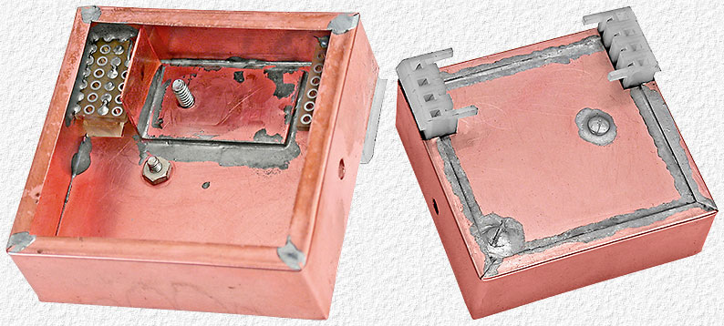
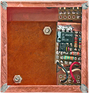
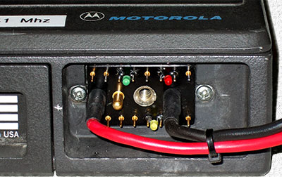
The channel element oven enclosure was made from sheet copper. Openings were cut in the bottom for two 4-pin Molex connectors that were soldered to small pieces of proto board soldered to 2 sides of the enclosure on the inside. The connectors are used to plug the oven into the receiver section of the radio using the pins provided for receiver channel elements at two of the channel element positions. |
|
 |
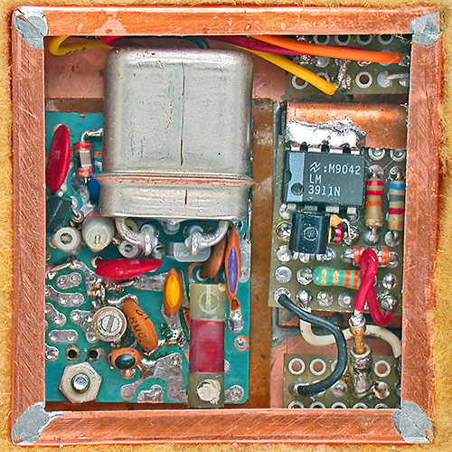
Upper Left - The heater is installed using a thicker piece of sheet copper with a 90° bend and mounting screw for the LM317 heater which is soldered into the enclosure as shown. Left - After installing the LM317 and controller board another 90° bend is made in the copper sheet tab which is then soldered to the controller board and pins 5 to 8 of the LM3911 as shown. The tab conducts heat from the enclosure to the pins which are tied thermally to the temperature sensor inside the LM3911.
The channel element is installed using two screws through the bottom with nuts on the inside that hold them in place and act as spacers. Two holes in the circuit board allow the element to then be simply dropped in place and secured with 2 additional nuts. |
 |
|
|
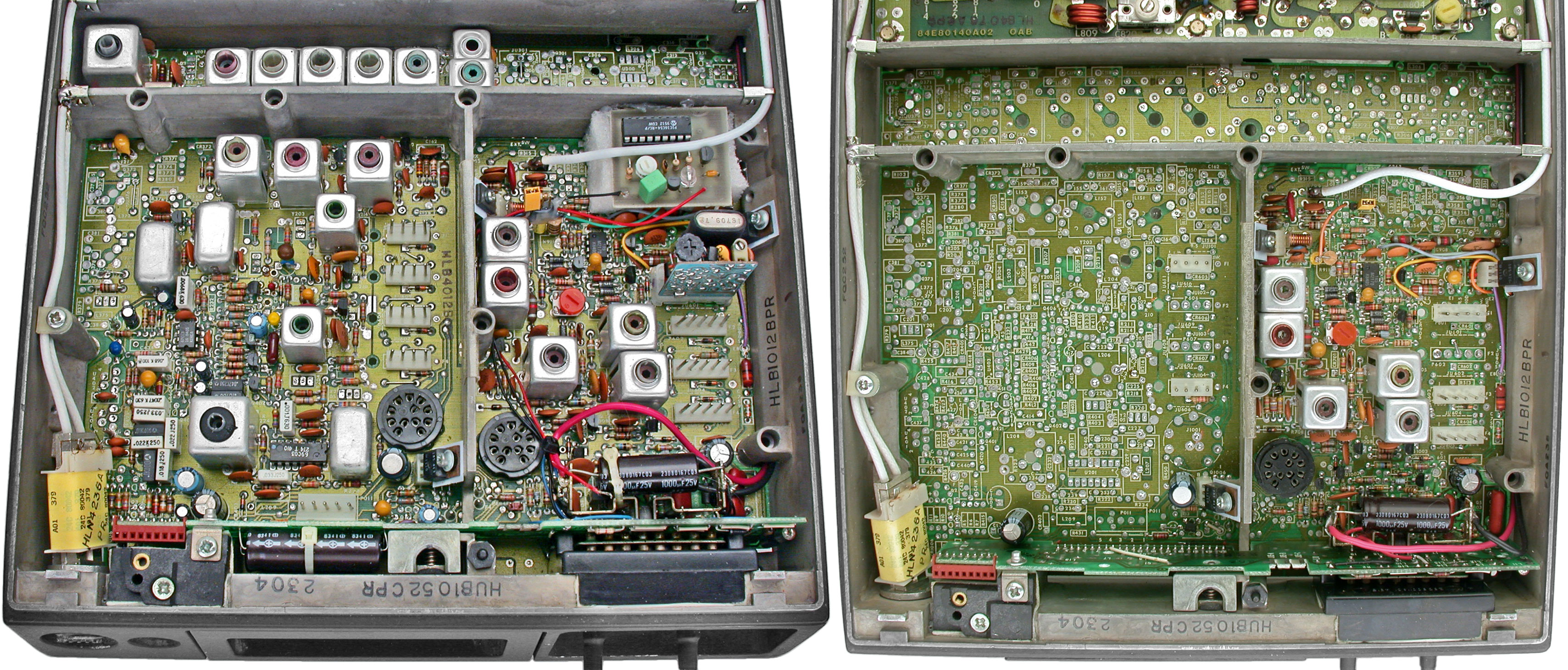
The only left before the OCXO is finished is to make a press-on cover from sheet copper with a small hole directly above the small trimmer capacitor to allow adjustment.
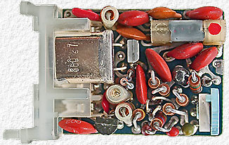
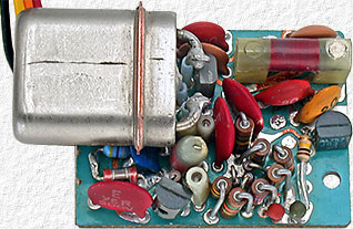
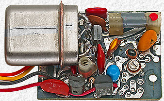
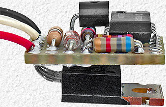
Left image above shows the radio before making any changes and on the right is after all, but a few, of the receiver components were removed to make space for the OCXO (Oven Controlled Crystal Oscillator). |
|
|
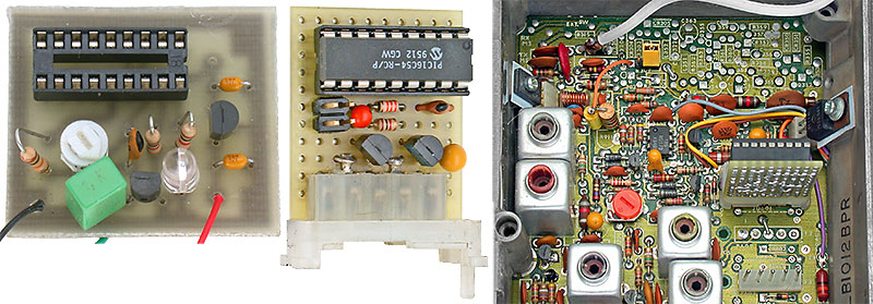
While removing the receiver components, the CW ID board along with the foam block and all of the silicon sealant used to install it were also removed in order to make whatever changes were needed in the transmitter section of the radio. The silicon sealant and block of foam got the job done, but silicon sealant isn't easy and a real pain to remove if one ever needs to work on something it's been used on and simply slipping the ID board inside a block of foam rubber large enough to be held in place between the circuit board and radio lid would have worked just as well. Anyway, while working with the channel elements I thought of a much better way to install the ID board and made a new circuit board for it that was much the same same size as a channel element board and turned the ID circuit into a plug-in module that now simply plugs into one of the otherwise unused transmitter channel element positions. |
|
|
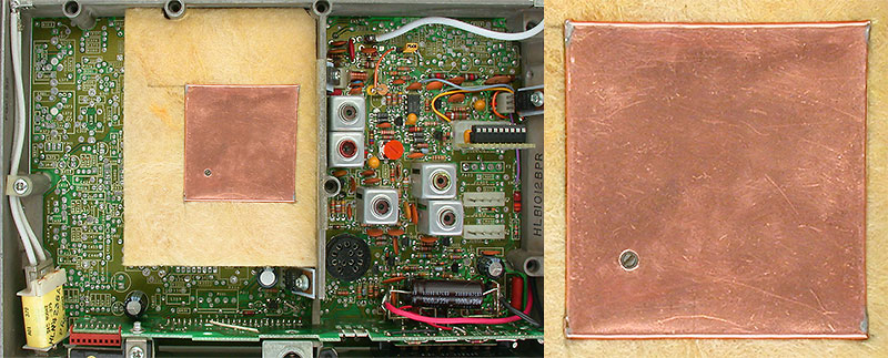
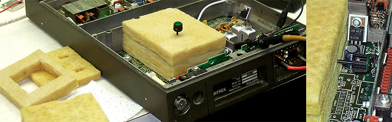
Insulation for the OCXO was cut from a fiberglass mat from an extra T-bar ceiling tile from which the plastic ceiling finish sheet was pulled off. One piece with 2 openings for the connectors was used under the enclosure, then several pieces with an opening for the enclosure are added and then a piece on top with one small 1/8" hole for a tuning tool. When the tuning tool isn't required a final piece with no openings is added on top which is sized in thickness so all the layers are held together by a slight pressure when the top of the radio is installed. The thickness of some other pieces, like the one under the enclosure, were also sized in thickness (reduced) as needed so everything fit just right. As seen in the right hand image above, one additional small 1/8" hole was provided in the insulation along the front edge of the stack for a tuning tool to adjust the elements inductor which adjusts the frequency. |
|
  |
|
|
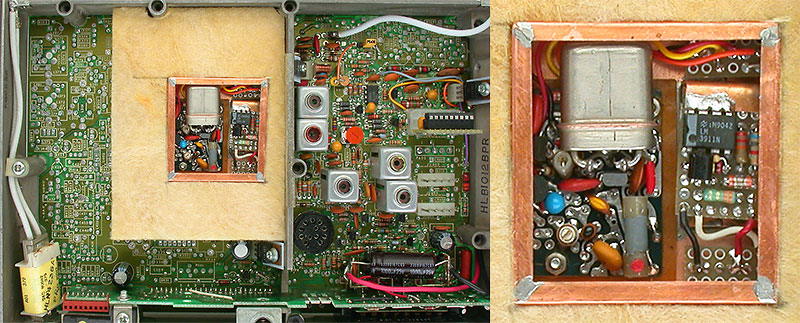
Left - How things look with the OCXO in the radio surrounded by insulation and with, and without, the oven enclosure top cover. |
|
|
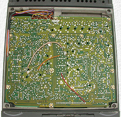
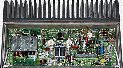
Heavy gauge power leads were soldered directly to the power pins on radio connector. Other pins were a convenient place to add Top Right - To make all of this happen, 3 jumper wires and a short length of miniature coax had to be added on the bottom side of the radio circuit board. A number of wiring changes were also made on the the top side of the main board and to the board the radio connector is soldered to, but I don't recall what they were exactly at the moment as, like I said earlier, it's been over 7 years since I did all this. Bottom right is an image of the RF power amp added simply because a bit more space was needed for text on this side. |
 |
 |
|
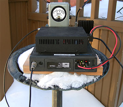 |
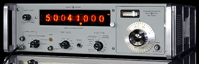
Above - The Frequency Counter in my workshop. Left - The Radio outside at −30°C (−22°F) while it and its new OCXO were being tested. The frequency counter was connected to the radio and showed its frequency remained the same regardless of whether the radio was inside at room temperature or outside at −30°C. Next: See what happened to the VE6EMU Tower not long after the beacon was finally back on the air. |
|
This OCXO project took several weeks longer to finish than it normally would have as it ended up with me having to actually work on and complete two OCXO projects. The HP frequency counter used and needed for the radio project was acquired not long before and I had not yet tried to use it and when I did I found its OCXO oven didn't work and it wasn't long before the oven repair turned into a major project that needed to be finished before I could continue with, and finish, the radio. |
||
|