 |
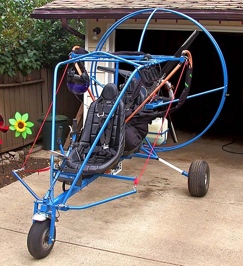
My friend Barry's July 2005 The PPC may appear to be too tall to fit inside my garage, but fits nicely and where it was while I finished a COM system for it and worked on a couple of problems for Barry. To get the PPC into the garage the propeller guard must be lowered a bit in order to clear the door frame, but this is easy to do by simply lifting the front wheel a few feet which has very little weight on it. |
VA6DX
|
|
|
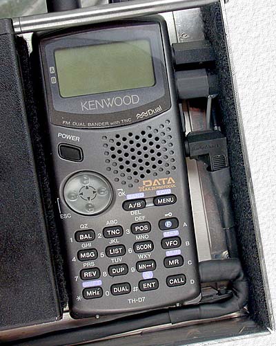
My friend Barry wanted to be able to communicate with others while flying his PPC, regardless of whether they were amateur radio friends using an amateur radio transceiver, others using a FRS transceiver and, of course, other pilots and air traffic control using air band transceivers and I offered to help him built a COM system for his PPC that would allow him to simultaneously use all 3 types of radios. From left to right, there's an Icom IC-A5 air band transceiver, a FRS transceiver, a cast aluminum box with the circuitry needed to make everything work together as one system, a RAD TAC100 dual headset intercom unit and a Kenwood TH-D7 VHF/UHF dual band amateur radio transceiver that can also be used for APRS. A common power switch was used to save having to turn each unit on or off individually and a common PTT switch was used for all 3 radios. The conductors seen tucked away behind the pink foam block along the left side of the Icom radio are for supplying power and COM system audio to an amateur TV transmitter in the future. The two 1/4" dia. rods seen between the TAC100 and the main aluminum enclosure upper front corners provide the missing enclosure corner needed for the enclosures fabric cover to fit properly. |
|
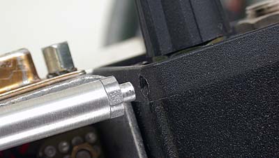 |
This photo shows how the ends of the 1/4" dia. rods are kept in place at the RAD enclosure corners by reducing the ends of the rods to 1/8" dia. and inserting them into 1/8" holes drilled in the enclosure corners. | |
 |
Other then two antenna connectors, a single 25 pin connector was used to connect the radio-intercom assembly to other wiring on the PPC to make removal, when the PPC is transported, and re-installation quick & easy. Wiring on the PPC includes connection to the PPC 12 volt battery, the common PTT switch on the throttle control handle, the COM system on/off power switch, LED power indicator and the radio selector switch on the instrument panel, the Stratomaster flight system alarm audio output and from a GPS receiver for use by the Kenwood radio for APRS. |
|
 |
||
 |
This low profile 25 pin connector on the end of the PPC wiring cable was a lot of work and took a fair bit of time to construct so I'm hoping it will stand up to all the vibration and other conditions it will be subject to. This connection is one that should have been planned more carefully so as to be able to use a standard height housing. | |
 |
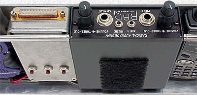
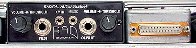
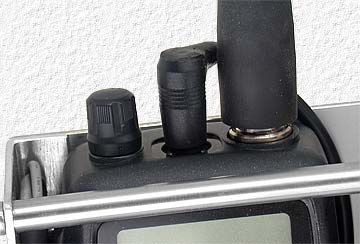
The RAD unit has a 3.5mm XMTR jack to provide pilot mic audio to a connected transceiver, but an additional 3.5mm jack was added to provide both pilot and co-pilot mic audio plus any received transceiver audio for future ATV transmissions. This audio plus 12 volts DC is available from a 4 pin mini-DIN in-line cable connector tucked away beside the Icom radio for when it's needed for a video camera and ATV transmitter. |
|
 |
Velcro fabric was applied to the side of the RAD unit and main aluminum enclosure to provide protection for the Kenwood radio & it's connectors. The RAD unit was then positioned for a snug fit to ensure that the radio plugs are kept firmly in place by the pressure the Velcro provides. |
|
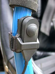
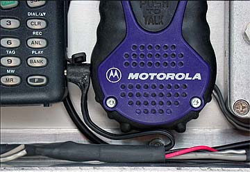
| (Right) The common PTT switch on the throttle handle |
 |
|
|
There were problems with the FRS radio connectors so they were removed and wiring was simply soldered directly to the radios circuit board. The Icom aviation radio connections appeared to be solid, but it had a strange problem and I eventually discovered that countless hours could have been saved trying to solve the problem if I had simply ignored the fact that it was a brand new much more expensive radio than the FRS and had also simply removed it's connectors and soldered it's connections directly to it's circuit board. The FRS radio was positioned to hold the ICOM radios power plug firmly in place. |
 |
|
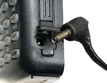
A right angle power plug could not be found for the Icom radio, but nothing an exacto knife, some creative carving and a little liquid rubber couldn't quickly solve. As mentioned above, countless hours were wasted trying to resolve constantly changing intermittent problems with the Icom radio that ended up being due to a less then perfect ground connection at both the coaxial power plug and 3.5mm spkr/mic/PTT plug. In future cases like this, with items that will most likely never be used for anything else and will be left permanently interconnected, I will certainly consider replacing all small plug connections with soldered ones much more seriously. |
 |
|
The Icom IC-A5 speaker/mic/PTT connection required a less common 3.5mm plug with 2 ring connections and a cable with a molded straight plug on each end was found and cut in half for a nice single ended cable to use for the IC-A5 plus a spare one for the next time I need to interface with something using a 3 circuit plug, like my FT-50. It would have been nicer if a cable with right angle plugs could have been found, but, like for the power plug, an exacto knife, some creative carving and a little liquid rubber quickly solved the problem. |
 |
 |
 |
|
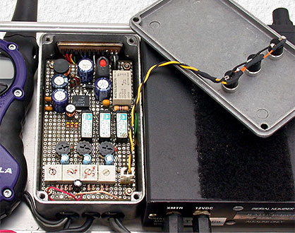
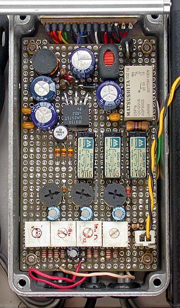
(Above) This is the circuitry required to interface with and control the different units. The three push-buttons on the front of the cast box are programmable TH-7D option buttons as explained in the Kenwood manual. (Right) Upper section is 12V DC power filtering and a switching voltage regulator that supplies 4.5 VDC for the FRS radio and GPS receiver. The remote power switch operates the grey colored relay that controls power to the COM system, the 3 smaller relays are PTT control relays, the 3 round pots are for adjustment of the audio level to each transceiver and the 4 square pots are for adjustment of the received audio level from each transceiver and the alarm tone level from the flight system. |
|
January 2015 I recently came across several unfinished pages and figured I may as well finish and publish them. The images were all laid out on this page when it was started in 2005, but this is as far as I got with the text before I got distracted and started on something else. It's hard to remember exactly what I was going to write about the following images, but I'll do my best to describe what they show. |
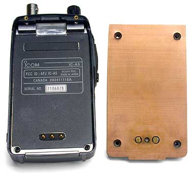 |
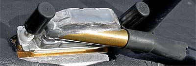
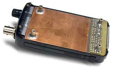
With the radio's being powered by the PPC battery they didn't require one of their own plus making a mounting plate that attached to the radio in the same manner as its battery did took care of how to mount the radio in the enclosure with everything else. This is the mounting plate made from .062" thick PC board material for the Icom radio. |
 |
|
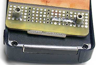 |
1/4" high threaded standoffs were used on the back side to attach the board to the main enclosure. The battery contacts were fashioned by attaching a piece of prototype board to the backside of the main mounting board. Note how the negative battery contact was tied to one of the standoffs at this point to help improve grounding to the main enclosure. The tab seen along the bottom edge of the mounting board slips under a ledge on the radio and holds the bottom of the radio in place. |
 |
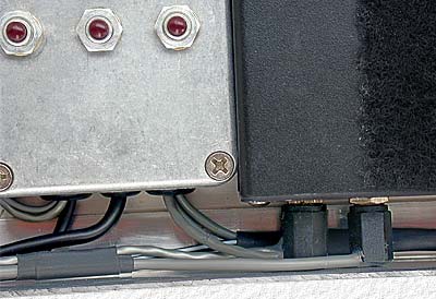
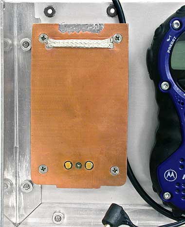
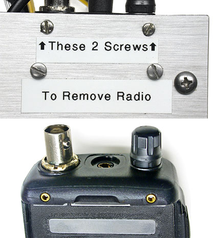
Left image shows the mounting board in place on the back of the radio with it held in place by the tab at the bottom. And the images below show how the radio is held in place at the top using 2 screws through the back of the main enclosure threaded into the 2 threaded brass inserts at the top of the radio back which are intended for a belt clip. It's hard to see, but salvaged 1/4" dia. threaded standoffs of the type found pressed into a panel to keep them in place were used where the 2 screws pass through the main enclosure to keep the screws from pulling the radio too tightly against the mounting board. |
 |
 |
|
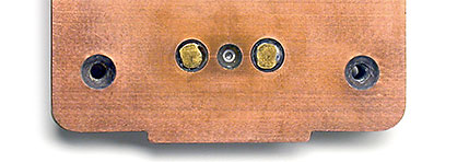
Above left can be seen some shielding braid removed from a piece of coax that was added to help improve grounding and located so as to contact the bare (unpainted) spot on the inside of the radio (grey area in bottom right image above). |
|
 |
|
|
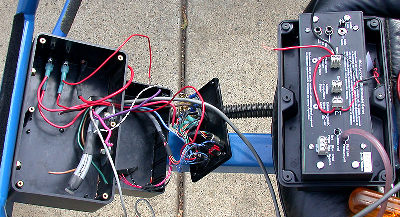
This final image is of the inside of Barry's Stratomaster flight system while it was being wired into the com system. (I wish I had an image of it all together to show, but unfortunately I don't.) |
|
|