 Tiny Tracks
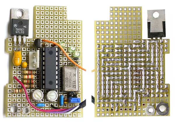 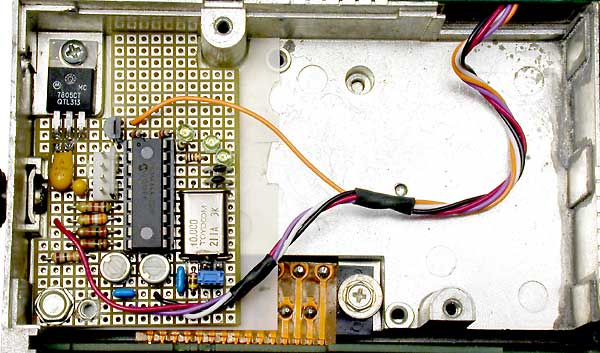 |
July 2002 Fred, VE3CFZ, dropped by with a MCX100 radio, a few GPS units and a TinyTrack circuit he had built for help getting an APRS tracker working for the used truck he bought while here and would be driving back to his home in VE3 land in a few days. After a day of problems, Fred left everything with me to continue working on. I figured the easiest way for me to quickly get everything working was to start fresh and build a new circuit which is seen here. It was made to be installed in the MCX100 where the CTCSS option is normally located and an ideal space with a raised area for a 7805 voltage regulator in the cast chassis. The board is held in place by the 7805 leads plus a screw into a cast circuit board standoff. |
 |
A 4 pin connector was installed to interface with a PC serial port during configuration and later with the GPS to supply it power and receive data from it.
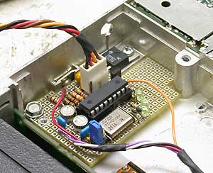
(below) A threaded post in the chassis casting and a blind nut installed in the circuit board are used to install the GPS circuit board. A sleeve placed over the screw threaded into the blind nut properly spaces the GPS from the TinyTrack circuit board. |
 |
|
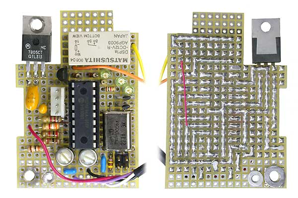 |
After the above photos were taken, a relay was added to provide a switched ground to the TinyTrack switch 1 input to reduce the beacon rate when the ignition is switched off. For a drawing of this circuit boards layout and of the inverter circuit: |
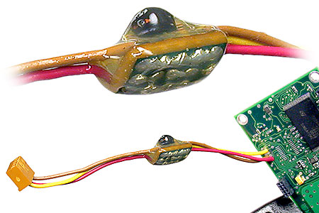 |
Murphy got me! Data from the GPS is regular non-inverted TTL serial data, but the TinyTrack interface is non-standard inverted TTL data designed for those with RS-232 output GPS receivers and PC RS-232 serial ports that will accept TTL level input data. The inverted data fact was overlooked while building the TinyTrack board and with no room to add an inverter on the TinyTrack board a separate 1 transistor and 2 resistor inverter was built and inserted into the 3 wire cable from the GPS to the TinyTrack. The assembly was then potted in hot glue to prevent shorts to the radio case and to provide strain relief for the wires. |
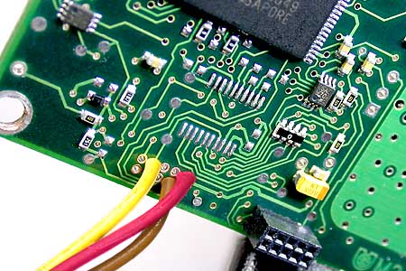 |
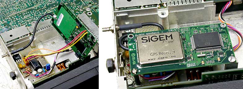
Components are getting smaller while my eye sight gets worse. Even with a tiny soldering tip, small diameter solder, fine wires and a big magnifying lens, it is still lots of fun to make connections to some items such as the GPS board. With no plug to match the GPS header socket, the socket was removed and the three required conductors were simply soldered directly to the board. Even with a plug, this was easier than trying to solder #28 wires to a plug with .020" pins spaced .040" apart and with no space for sleeving to prevent shorts. The only reliable way to use connectors this small is to crimp pin connections using the proper crimp tool, however this is not practical for hobbyists. |
|
With every different connector pin type requiring a different crimp tool and with each proper crimp tool costing several hundred dollars, explains why I solder interconnecting wires directly to boards with other then standard connectors and pins that I am able to crimp or solder. I then install a standard inline connector where required to allow items to be repeatedly removed and reinstalled. Fred is now on his way back home to VE3 land and beaconing his position as he travels and tries out every IRLP node between Edmonton and Toronto. He gave me some GPS units and I have TinyTrack chips to use so I'm off to the work bench to turn several of my MCX100's into trackers now that I've worked out exactly how to do this with Fred's radio. |
|
![]()
|