|
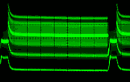
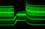
Waveform Effects |
|
Component Designations (i.e. R1, C1, L1, etc) refer to components on my 13cm and 23cm Receiver Schematics. Gold Mod 3(b) to improve picture quality added a 0.1 ufd capacitor across a .05 ufd video coupling capacitor (C8) in the receiver in an attempt to improve the low frequency response. This is the Gold mod that created the frame lock / vertical hold problem |
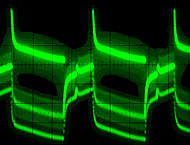 |
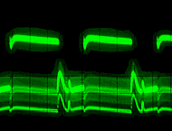
Un-modified 23cm Transmitter Receiver Output |
 |
|
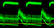
The received signal from the tuner is centered about the average signal level due to the transmitter's poor low frequency response. With C8 = .05 ufd, the receiver's clamping circuit is able to provide some signal restoration. |
||
|
(Gold modification adds a .1ufd to .05ufd ( = .15ufd ) |
|
 |
|
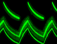
Increasing C8 to .1 ufd improves the receiver's low frequency response, but this results in more waveform distortion which creates the vert hold problem. |
||
|
To extrac sync from the video signal, sync circuits typically compare the waveform to a DC reference level (indicated by yellow line) which is set slightly above the sync tip level. Signals that do not cross through the reference level are not detected. As can be seen, if the sync do not remain at a constant level, it is not going to be detected. |
||
 |
Modified 23cm Transmitter Receiver output |
 |
|
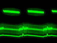
The transmitted waveform seeks the average signal level more slowly now and over the whole field rather than just a few lines. This doesn't require as fast a restore circuit so waveforms are improved. |
||
|
|
 |
|
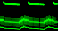
Even with C8 increased to .1 ufd, the sync level remains fairly consistant and monitors show no vertical hold problems. |
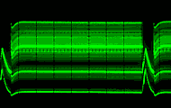
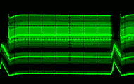
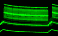
| The following waveforms show the effect of transmitter low frequency mods using a Multi-Burst waveform which is a more typical video waveform. |
|||
| Standard Transmitter | Modified Transmitter | ||
| C8 = .047 ufd | C8 = 1.0 ufd | C8 = .047 ufd | C8 = 1.0 ufd |
 |
|
 |
 |
|
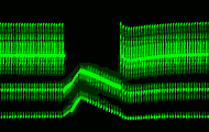
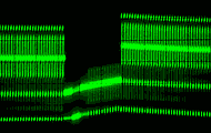
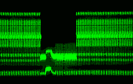
Photos Below Are Close-up |
Views Of Above Waveforms |
||
 |
|
 |
 |
|
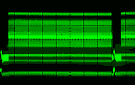
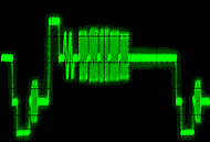
Field rate waveforms (right) with C8 = .01 ufd may appear improved from the waveforms above, but line rate waveform effects due to reduced low frequency response can be seen in the waveforms below. |
 |
 |
|
| With C8 = .01 the waveform appears improved, | |||
 C8 = 10 ufd |
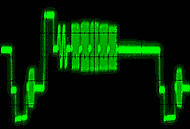 C8 = .047 ufd |
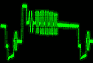 C8 = .01 ufd |
but line rate waveforms (left) show the effect of reducing the frequency response. |
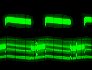
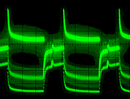
Below are more waveforms showing the effect of various C8 values on received video.
| Received Waveforms from an Un-modified Transmitter | ||||
| C8 = .01 ufd | Original C8 = .05 ufd | C8 = 0.1 ufd | C8 = 1.0 ufd | C8 = 10 ufd |
 |
 |
 |
 |
 |
|
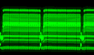
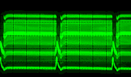
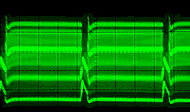
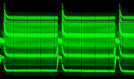
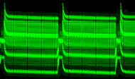
Square Wave Waveform was used to emphasize low frequency distortion during Vertical Sync Period |
||||
 |
 |
 |
 |
 |
|
Multi-Burst Waveform was used for a more typical Vertical Sync Period The waveform clamp (DC restoration circuit) is too slow for quickly changing waveforms. |
||||
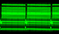
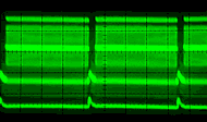
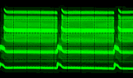
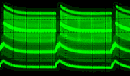
| Received Waveforms from a Modified Transmitter | ||||
| C8 = .01 ufd | Original C8 - .05 ufd | C8 = 0.1 ufd | C8 = 1.0 ufd | C8 = 10 ufd |
 |
 |
 |
 |
 |
|
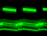
Square Wave Waveform (above) emphasizes low frequency distortion during Vertical Sync Period |
||||
 |
 |
 |
 |
 |
|
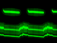
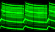
Multi-Burst Waveform (above) shows more typical Vertical Sync Period waveforms The waveform clamp is able to improve the more slowly changing waveforms better. The waveforms with C8 = 10 ufd are basically the same as the tuner's output waveform. The waveforms show that the circuit time constant is too long with C8 larger than ≈ 0.1 ufd for the waveform clamp to be effective. A C8 of .05 ufd is sufficient to provide a fair low frequency response for line rate video waveforms so C8 was left at it's original value of .05 ufd. |
||||
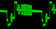
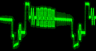
| Line Rate Video Waveforms | |||
| Un-Modified Tx | Modified Tx | Un-Modified Tx | Modified Tx |
 |
 |
 |
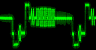 |
| C8 = .01 ufd | C8 = .05 ufd | ||
|
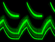
These waveforms show that improving the low frequency response of the transmitter and receiver, by increasing C8 from the receiver's normal .05 ufd value, makes little difference to the line rate video waveform. C8 could be increased for better signal waveforms with a better video DC restoration circuit which is something I will work on for a future project. |
Un-Modified Tx | Modified Tx | |
 |
 |
||
| C8 = 10 ufd | |||
