Platinum
23cm Gold Receiver
Remove Gold Mods Mod |
|
G1MFG Links:
|
Mod Page -
Mod Page -
Gold Mods -
Gold Mods -
Gold Mods -
Mod Page -
|
Improve received picture quality (1)
Improve received picture quality (2)
Improve picture quality (3)
Improve picture quality (4)
Improve sound sensitivity
Improve sound demod sensitivity
|
|
Note: All links to g1mfg.com have been removed from this page as the web site no longer exists.
|
|
REMOVE: G1MFG Mod Page - Improve received picture quality (1)
|
| Component designations (i.e. R1, C1, L1, etc) refer to components on my 23cm Receiver Schematic. |
|

|
This mod reduces the receiver's high frequency response and should be removed.
|
|

|
To Remove This Modification:
Remove the 470 pfd capacitor that was added across R3.
|
|
This Modifications Problem
is that 470 pfd capacitor added across R3 makes received video "appear" less noisy by reducing the receivers high frequency response. This limits high frequency noise, but also limits the amount of color information and fine picture detail being received.
I was surprised to see a color picture on my monitor after noticing how little color signal one Gold receiver was providing (4th waveform below). Removing this capacitor from Gold receivers makes a significant improvement.
For those not concerned with fine picture detail or color and like to pretend that they have P5 reception, they can either leave the capacitor in or resort to their monitor's sharpness control to filter out noise.
|
Signal Generator
3.58 MHz Color Burst |
Basic 23cm Receiver
Color Burst |
23cm Gold Receiver
Color Burst |
Gold Receiver #2
Color Burst
|
| Horizontal Sync and Color Burst from Signal Generator, Standard Receiver and 2 Gold Receivers. |
|
Basic Rx
|
Basic Rx w/470p
|
(Left) 23cm Basic Receiver Waveform. (Right) Basic Receiver with this modification.
The 470p capacitor limits the receiver's high frequency response which leads to loss of detail and weak color.
|
Platinum Receiver
Waveform |
Waveform with 470 pfd capacitor across R3. |
These waveforms show what a 470 pfd capacitor would do added to a Platinum Receiver.
1st waveform is normal Platinum received waveform.
2nd waveform shows the effect the 470 pfd capacitor has on frequency response.
|
|
The g1mfg.com de-emphasis article (page 3, install step 5) says "this capacitor is NOT used to ‘flat-top’ the frequency response: it’s required to make the NE592 amplifier more stable."
This capacitor certainly does not ‘flat-top’ the frequency response! Rather, it provides a nice downward slope to the frequency response curve! In MANY hours of experimenting to improve the receivers frequency response, I never saw any examples of amplifier instability.
|
 |
I can not resist asking -
What good is a stable video amplifier that doesn't pass Color Burst & Chroma Information?
|
|
REMOVE: G1MFG Mod Page - Improve received picture quality (2)
|
|
This is the Increased Sensitivity Mod that gave >3 dB sensitivity improvement for weak signals and WAS my favorite Gold modification. After the other mods were found flawed, it remained and appeared to be the one Gold modification that worked - until a problem
was found with it also.
|
|
|
This mod reduces the video detector deviation acceptance and should be removed.
|
|
To Remove This Modification:
Remove the 10K resistor between ground & pin 14 of the 30 pin I.C. in the tuner.
|
| The following info was written for the installation of this mod before it was found to cause problems. Information that remains relevant has been left as an intro to the following mod problem description. The receiver sensitivity table
shows this modification reduced the signal required for P5 reception by 1 dB and provides 3.3 dB additional receiver gain for weaker signals (0.1 volt noise level). Substituting a 8.2K resistor for the 10K provides even more (5 dB) receiver gain for weaker signals, but don't try to push a good thing to far as less than ≈ 8K
will cause the receiver to stop functioning.
|
 |
Giles reported that
"We don't yet know why this one works" and
"Some receivers go a little off-tune with this mod"
 Why it works - Why it works -
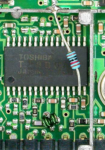
The TA8804F is a receiver I.C. Pin 14 is one of the 2nd AGC Filter pins, pin 15 is the other. If pin 15 is connected to +5V (Vcc) the AGC will be minimum gain and the PLL FM detector VCO will oscillate at its free-running
frequency. Since the 2 pins are the input to a differential circuit, pulling pin 14 to a lower voltage will increase the AGC gain, but if pulled too low the VCO will become free-running and the receiver will no longer demodulate received video. I found that a slightly lower value of resistor could be used for even greater
receiver sensitivity, but < ≈ 8K will cause the VCO to free-run. See the receiver sensitivity table to study the effect that this resistor has on receiver sensitivity and the 2nd AGC voltage (signal voltage column).
The frequency shift is due to imbalance in the PLL video detector circuit caused by the 10K resistor connected to one of the circuits differential inputs. The VCO frequency shift makes it appear as if
the receiver is off frequency, but this can be corrected by a very small adjustment of the VCO oscillator coil.
(PLL FM detector VCO oscillator Coil is the
small green coil at the bottom-center of photo)
|
| This Modifications Problem |
 |
Un-Modified Tuner
Base-Band Video.
|
 |
Increased Sensitivity
Gold Modified Tuner
Base-Band Video.
|
| As mentioned above, the 10K resistor connected to one of the two differential inputs to the PLL video detector causes an imbalance in the circuit which shifts the detector's VCO frequency slightly. However, this also reduces the video deviation level that the PLL is able to accept which leads to waveform
distortion at the top and bottom of the video waveform (modulation extremes). Since the modification causes the VCO frequency to increase slightly, the distortion will be noticed first along the lower edge of the waveform unless the frequency shift is compensated for by retuning the VCO oscillator or tuning the receiver slightly
higher in frequency. The receiver is still usable with this modification at lower deviation levels, but this will result in higher noise levels. Conclusion: It's best not to upset and un-balance differential circuits. |
|
REMOVE: G1MFG Mod Page - Improve picture quality (3)
|
|
Component designations (i.e. R1, C1, L1, etc) refer to components on my 23cm Receiver Schematic.
|
|
|
Part "A" of this modification does not appearto be relevant any more.
Click here to see if you can make sense of all the conflicting G1MFG Information.
|
|
To Remove Part "A" of this Modification ( If L1 or L2 are shorted out ):
Remove the short,
then see the Video Band Pass Mods for correct circuit & component values.
|
|
|
Part "B" of this modification increases the value of C8.
This is the Gold modification that creates the frame lock / vertical hold problem.
|
|
To Remove Part "B" of this modification:
Remove the 0.1 ufd capacitor across C8,
then do the Transmitter and Receiver
Improve Video Quality Mods
|
|
The effect of C8 on waveforms can be seen HERE.
|
|
REMOVE: G1MFG Mod Page - Improve picture quality (4)
|
|
Component designations (i.e. R1, C1, L1, etc) refer to components on my 23cm Receiver Schematic.
|
|
This Gold modification changed R8, a 150 ohm resistor to 75 ohms.
To Remove This Modification:
Remove the 150 ohm resistor in parallel with the original 75 ohm resistor
(UNLESS using a CIRR de-emphasis network that requires a 75 ohm source impedance.)
If using the receiver's normal L/C filter to remove the audio sub-carriers from the video,
this resistor must be 150 ohms to provide proper filtering.
See Platinum 23cm Receiver - Improve Video Quality Mod for correct
component values for receiver video and audio
filter circuits.
|
|
REMOVE: G1MFG Mod Page - Mod to improve sound demodulator sensitivity
 (and on) Gold Mods Page
- Improve sound sensitivity (and on) Gold Mods Page
- Improve sound sensitivity
|
|
Component designations (i.e. R1, C1, L1, etc) refer to components on my23cm Receiver Schematic.
This Gold modification adds an 82 pfd capacitor to C10 of the audio sub-carrier band pass filter.
To Remove This Modification:
Remove any extra capacitors added to C10.
Then see Platinum 23cm Receiver - Improve Video Quality Mod
for correct component values of audio sub-carrier filter.
This is another Gold modification that was not done on my Gold receivers.
If this modification no longer applies then it would be nice if some information were posted to that effect or the modification should be removed from web pages!
C10, L3 & C11 make up the audio sub-carrier filter that removes the sub-carriers from the video
and passes them on to the audio demodulators.
|
|
If this modification is valid, my Gold receivers should have come with a 82p capacitor stacked on the original capacitor (C10) or if C10 was replaced (rather than stack capacitors) it should have been >82pfd. My 23cm
(standard & Gold) receivers came with 56 pfd capacitors but the 13cm receivers came with 20 pfd capacitors, the value shown on the Comtech schematic.
The 13 & 23 cm receiver filter circuits and sub-carrier frequencies are identical, so why do they have with different component values? They can not both be correct!
The incorrect reasoning behind adding an extra capacitor to C10 is that this would lower the circuit's series impedance and pass more sub-carrier signal to the demodulators. The secret to the filter is not to make the series path a lower impedance but
to make the L3 impedance, that shunts unwanted signal to ground, a higher impedance near the sub-carrier frequencies. Adding 82 pfd to C10 will shift the resonant frequency lower and result in less sub-carrier and more video reaching the demodulators.
See Graph to the Right ► ► ► ► ►
Center Freq is 6.25 MHz with C10 = 20 pfd (Red plot)
Center Freq is 5.37 MHz with C10 = 56 pfd (Yellow plot)
Center Freq is 4.76 MHz with C10 = 102 pfd (Green plot)
|
Audio Sub-Carrier Filter
Frequency Response Graph |
 |
These are computer generated plots of the audio sub-carrier band-pass filter response.
Red Plot is with Platinum circuit values of -C10 = 20 pfd, C11 = 100 pfd & L3 = 6.8 uH Center Frequency = 6.25 MHz
Markers are at 6.0 MHz & 6.5 MHz
Horizontal Freq Sweep is 1.0 to 10 MHz
Changing any of the 3 component values will shift the resonant frequency and cause one or both of the demodulator sub-carrier freq's to become less.
|
| |
|