ATV Receiver "S" Meter &
Expanded Volt Meter Mod
 |
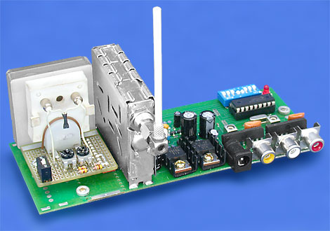
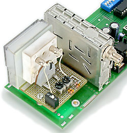
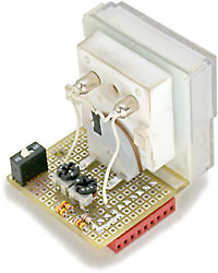
If the receiver tuner is installed upright, a perfect space is created for a "S" meter.
If you wish to monitor battery voltage, you can add an expanded volt meter function to the meter also. Small audio level meters can be salvaged from old equipment and are perfect for this use. The more sensitive meters are best. The ones I used were 200 uA. |
 |
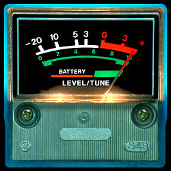
(left) "S" meter |

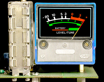 |
For dual function use, a second switch selects between "S" Meter and Expanded Volt Meter. This expanded volt meter begins to indicate |
| Start by removing the tuner and the 15 pin header strip from the receiver circuit board. |
|
For 23cm receivers only - |
||
| (1) See 23 cm Receiver Mod's for how to make the signal strength voltage available on one of the tuners pins. | ||
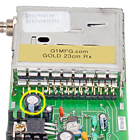 |
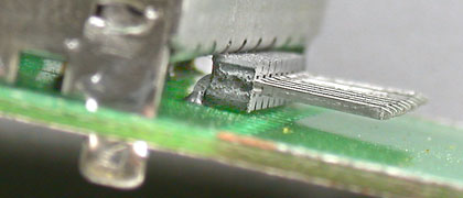
(2) The 220 uF capacitor (circled in yellow) needs to be replaced with one no larger than 1/4" in diameter to permit the tuner to be installed vertically. The new capacitor voltage can be anything greater than 6 volts. |
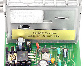 A 220 uF, 10V, 1/4" diameter capacitor with 1/8" lead spacing was used here. |
 |
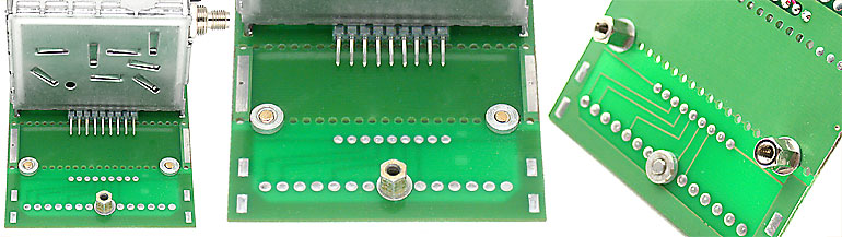
Next install a 9-pin right angle header strip in the circuit board holes which will end up under the outer edge of the tuner when it is installed.
The meter assembly is attached to the receiver by this header strip and one 4-40 screw. The tuner can now be installed vertically, in it's new location. |
 |
|
 |
Next drill holes and install four #4-40 standoffs on the top side of the board and one on the bottom as seen in the photos. I used blind nuts, removed from old equipment, to install the standoffs. The four bottom standoffs serve as receiver feet or they can be used to fasten the receiver into an enclosure. The upper standoff will be used to secure the meter assembly. The standoffs were salvaged from old computer D-sub type data connectors. |
|
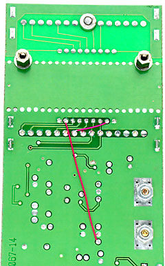
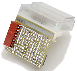
| (left) Two jumpers are required to connect the "S" meter signal and the receivers supply voltage to the meter header strip.
(right) A Molex side entry board connector is used to mate with |
|
|
 |
Basic "S" Meter Circuit You may need to select a higher or lower value for the 14K resistor if using a more or less sensitive meter. With no received signal, the signal level voltage will be between 0.8 and 1.4 volts, depending upon the receiver. The 1K resistor, diodes and 500 ohm trimmer provide an adjustable offset voltage to allow the meter to be set to read zero. The 5K trimmer can then be adjusted for a full scale meter indication while receiving a strong signal. |
|
"S" Meter and Expanded Volt Meter Circuit
|
  |
 |
|
| "S" Meter | "S" Meter Circuit Board | "S" Meter / Battery Voltage Meter |