|
Receiver & Transmitter Mods
|
|||||||
|
I started my FM ATV adventure using a standard 23cm receiver. Everything was ok until I tried a Gold receiver. Since, I have spent a significant amount of time investigating problems to make my Gold receivers useable. This page describes my long DETOUR from other projects to fix a problem with the Gold receiver that eventually resulted in the Platinum Modifications and improvement mods for all of the G1MFG 13cm & 23cm receivers and transmitters. These modifications may also apply to similar Comtech units from other suppliers. This page is to share my modification experience, information and hopefully make a worthwhile contribution to on-line information. On this page
If you have a Gold receiver, check out the Remove Gold Mods Mod that shows why
Note: The g1mfg.com web site no longer exists so previous links to site have been removed. |
|||||||
|
Also Note: Much has changed since these pages were written. I don't believe Comtech Rx's & Tx's are any longer available and there's now much better equipment designed for R/C aircraft FPV to use, but the pages are being left for those that still have and use Comtech units to reference. And for those still using these Comtech units, please note that the vertical sync problem is actually a transmitter design problem that's next to, if not impossible, to correct and that the receiver mod's are simply an attempt to try and make the problem less sever. |
|||||||


|
I know how much work and time is involved in maintaining a web site, so I normally excuse a few errors or disparity. P.S. It was never my intention to discredit the Gold mods during investigations. |
|
Data Sheet, Schematic & |
|||
|
It was very difficult to find any technical information, other than what |
|||
| 13cm Receiver Schematic |
23cm Receiver Schematic |
13cm & 23cm Transmitter Schematic |
|
| 13cm Tuner Partial Schematic |
23cm Tuner Partial Schematic |
13cm Tx Module Partial Schematic |
23cm Tx Module Partial Schematic |
| FM2400RTIM8B.pdf 13cm Tuner Data Sheet |
FM1394RTIM.pdf 23cm Tuner Data Sheet |
FS2400TSIM.pdf 13cm Tx Module Data Sheet |
FM1394TSIM.pdf 23cm Tx Module Data Sheet |
| SP5055 Data Sheet |
SP5055 App. Note |
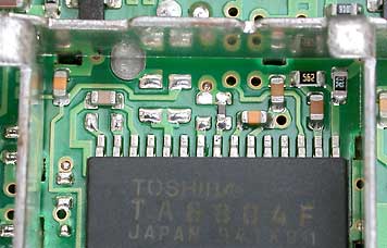
TA8804F Tuner I.C. |
TL592 OpAmp |
KIA6003S Audio Demodulator I.C. |
NJM2360 DC/DC Converter |
|
||||||||||||||||||||||||||||||||||


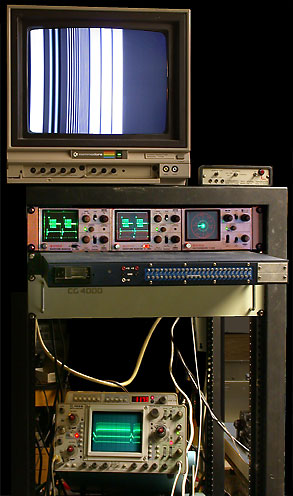 |
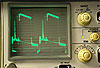
Test equipment setup while working
With such interesting electronics available it is easy to |
Giles at G1MFG has his "Gold" modifications and now I have some of my own, but they need a name.
Someone suggested to use what the credit card companies use to indicate better than Gold, so here are
|
The Platinum Modifications |
Note: These modifications are not for everyone and many will require Warning! Perform these modifications at your own risk! Use the following links to quickly locate individual modifications and other information.
Modifications are quite simple and only require changing a few components, so don't let all of the waveforms and information scare you away from trying these mods. I wanted to document, for my own reference, what I found and I may have included more than necessary of the 400+ recorded waveform images. I hope explanations are clear and thorough enough to properly explain things and answer any of your questions. |
| Before and After Platinum Modification Waveforms |
| Receiver & Transmitter Waveforms Before Platinum Modifications | After Platinum Mods | ||
| 13cm Advanced | 23cm Basic | 23cm Gold | 13cm or 23cm Rx & Tx |
 |
 |
 |
 |
|
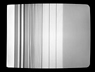
Field Rate Multi-Burst Signal shows typical Vertical Sync Period Waveform. The un-modified 13cm receiver video is very good. The 23cm Basic receiver is worse due to poor low frequency response of the transmitter. The Gold mod that increases the value of C8 in the receiver makes the receiver's output worse, to the point that the receiver becomes unusable due to the vertical hold problem. |
|||
 |
 |
 |
|
|
Field Rate Square Wave Signal to enhance DC Restoration Problems. The un-modified 23cm units have trouble handling a signal of this type. Even though the received waveform from Platinum modified receivers is less than ideal, other equipment seems to have no problem dealing with it. |
|||
 |
 |
 |
 |
| Line Rate Multi-Burst Signal to show the Frequency Response of Transmitter/Receiver Pairs. Un-modified units show poor high frequency responses. Platinum modified units show a fairly flat response. |
|||
 |
 |
 |
 |
| Horizontal Sync and Color Burst Signal. The Platinum modified units provide a much cleaner output signal with no discernable overshoot or ringing. |
|||
|
|
13cm and 23cm Platinum Receiver Waveforms |
 |
|
|
| 13cm Receiver | 23cm Receiver |
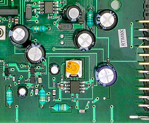
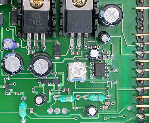
| Platinum 13cm & 23cm Transmitter Voltage Regulator Mod |
|
|
Reference: Transmitter Schematic |
|
 |
The manual says "power requirements are 12 to 18 VDC at 150 ma and best results are with a supply of 15V or more" because the 78XX series of regulators require up to nearly 3 volts greater input voltage than output voltage, to provide regulation. |
| The stock 7812 regulator is not a problem when operating from an unregulated 12V wall-wart that is capable of supplying greater than 15V to a 150 ma load. However, when operating from a 12V battery or regulated 13.8VDC power supply it is best to replace the 7812 with a low dropout regulator such as a LM2940 which requires 12.2V, or less, input to provide a regulated 12V output. If you always use a regulated 12V power supply, one could also simply remove and bypass the regulator. | |
| Platinum 13cm 8mW Transmitter - Increase Power Mod |
|||||||||||
|
|||||||||||

| Platinum Transmitter Video Peaking Information |
| Component designations (i.e. R1, C1, L1, etc) refer to components on 13cm Transmitter Module Schematic and 23cm Transmitter Module Schematic |
||
|
In the transmitter modules, video goes through a parallel C1-R1 (100p // 2.7K) video peaking network before going to VR1, for deviation adjustment, and through C2 to the modulator. |
||
 Waveform Before C1//R1 |
 Waveform after C1//R1 |
Waveforms show the effect of |
 Received Waveform Without Peaking |
 Received Waveform With Peaking |
Received Multi-Burst Waveforms |
|
The C1//R1 video peaking circuit effect is removed in the receiver by a series C-R circuit. This is likely some form of noise reduction pre-emphasis, however between manufacturers there seems to be no standard as to the amount of peaking applied. This presents a problem for ATV groups where equipment from any number of different manufacturers could end up being used.
I would appreciate hearing from anyone who has answers for any of the above questions or how different groups have addressed this problem. I would also appreciate hearing from anyone who has good links to information regarding this topic. Any information received will be shared with everyone here. |
||
| Platinum 13cm Transmitter - Improve Video Mod |
|
Component designations (i.e. R1, C1, L1, etc) refer to components on 13cm Transmitter Module Schematic. |
| Platinum 23cm Transmitter - Improve Video Mod |
|
Component designations (i.e. R1, C1, L1, etc) refer to components on 23cm Transmitter Module Schematic. |
|
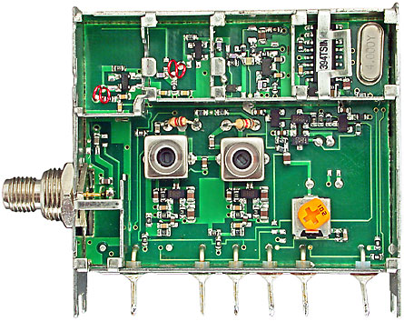 |
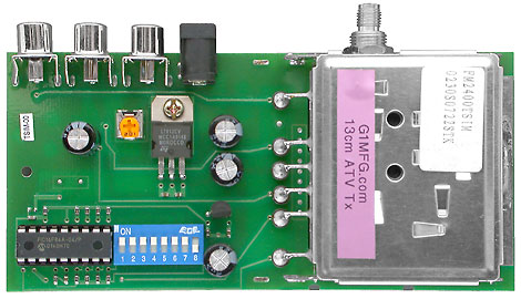
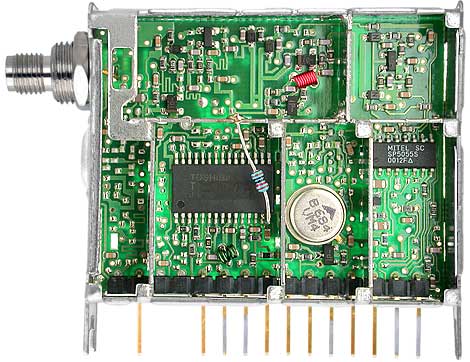
23cm Transmitter Module Comtech FM1394TSIM 1340-1450 MHz 40mw (typical)
NOTE: This mod will make the Gold receiver vertical hold problem worse, so the Gold receiver mods must be removed. Then keep going and do it right by performing the Platinum receiver mods. |
 |
Place cursor over text to show For access into the PLL compartment, this this tab must be temporarily bent up and out of the way. Replace 36 pfd capacitor at this location with a .01 ufd capacitor. The 36 pfd cap is so tiny that it is easiest to replace it. Photo shows a larger .01ufd cap. used for mod. Stack & solder a 0.5 ufd capacitor on top of the 1.0 ufd capacitor at this location or simply replace the 1.0 ufd capacitor with a 1.5 ufd one. It is usually easiest to simply stack & solder components if they are of similar physical size. Replacing this 1.0 ufd capacitor with a 2.2 ufd 6.3V capacitor will make a further slight improvement to the transmitter low frequency response, but the improvement is too small to make this mod worth doing. Video Peaking Components C1 & R1. VR1 Video Deviation Control |
|
This Modifications Effect |
||
 |
 |
Received Field Rate Waveforms |
 Un-Modified Transmitter |
 Modified Transmitter |
Close-Up of Waveform Vertical Sync Period After modification the sync level remains more |
| The low frequency response problem is caused by a 36 pfd capacitor being too small a value, in comparison to the varactor capacitance, to effectively modulate the varactor diode at lower frequencies.
Increasing the value of the 36 pfd capacitor also increases the PLL response time. This makes it impossible for the PLL to correct large frequency step changes so the PLL filter 1.0u capacitor must be increased in value to reduce the response time. Before increasing the 1.0 ufd capacitor's value, it was interesting to watch received video fluctuate for a second or more while the transmitter's PLL corrected small transmitter frequency changes. It is nice to have frequency agile transmitters, but PLL circuits in FM video transmitters can be a big problem. Think about it. First, we want a PLL with a fast response time to quickly respond to transmit frequency changes. Even if we don't mind waiting, the response
time must be at least fast enough to correct for the largest frequency step change that will be made. Then, when we modulate the VCO with video, we want a PLL with a slow response time that will not correct the VCO frequency changes due to FM modulation. We can not have it both ways so compromises
must be made. So if you want a good FM video transmitter, forget about being frequency agile and use a crystal oscillator type transmitter. |
||
| Platinum 13cm Receiver "S" Meter Output Info |
|
 |
13cm Tuner "S" Meter Signal This voltage varies from ≈ 0.9V (no signal) to 4.3V (AGC saturated). See Receiver Sensitivity Table for See "S" Meter Mod for details of how to add a "S" meter. |
| Platinum 23cm Receiver "S" Meter Output Mod |
 |
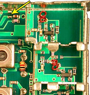
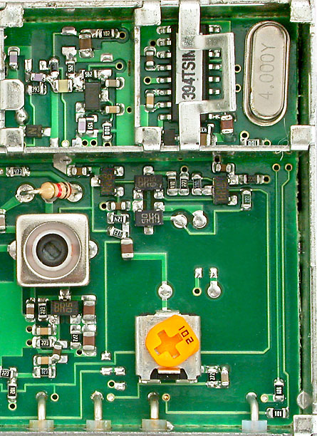
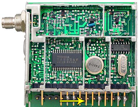
23cm Tuner The 13cm & 23cm tuners look (and are) very similar. A signal strength voltage is available on pin 19 of the TA8804F receiver I.C. in the tuner. Unlike the 13cm tuner, a jumper must be installed to make the "S" meter signal available on pin 9 of the tuner. See Receiver Sensitivity Table for |
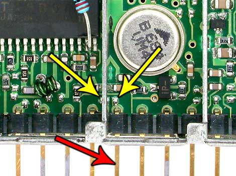 |
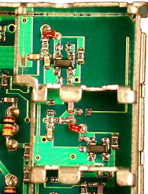
This modification is the G1MFG "S" Meter Mod, with some additional information. In the tuner, locate the two pads (indicated by yellow arrows) on either side of a compartment 'wall'. There is just enough room under the wall to solder a small wire link between the pads. The signal strength voltage will now be on pin
9 of the tuner (indicated by red arrow). |
|
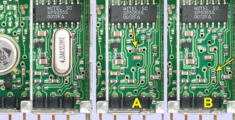
The G1MFG "S" Meter modification fails to mention that pin 9 of the tuner is connected through a 220 ohm resistor to pin 10 of the SP5055 PLL I.C. This has no effect on the signal strength voltage, but if one ever wanted to make use of the PLL I.O. signal, then it would need to be relocated. Fortunately, it is easy to relocate the PLL signal to the same tuner pin that the 13cm tuner has this signal available on. |
 |
|
1. Remove the 4 MHz crystal. |
| Platinum 13cm & 23cm Receiver - Improve Sensitivity Mod |
|
|
| There is a problem with the Gold receiver sensitivity modification, but when I have more time I will see if there is another way to improve this and the 13cm receiver sensitivity some. The receivers, which already have better sensitivity than any other receivers that I know of, have no sensitivity problems, but it is always fun to try and find free improvements. As for weak signals, the extra 3 dB gain provided by the Gold mod will not really make that much difference compared to a good 16 dB low noise pre-amp installed at the antenna. |
| Platinum 13cm Receiver - Improve Video/Audio Mod |
|||||
|
|||||
| Platinum 23cm Receiver - Improve Video/Audio Mod |
||||||||||||||||||||||||||||||||||||||||||||||||||||||
|
|
||||||||||||||||||||||||||||||||||||||||||||||||||||||
|
||||||||||||||||||||||||||||||||||||||||||||||||||||||
| Platinum 23cm Receiver - Add AFT Output Mod |
|
Refer to 23cm Receiver Tuner Schematic This mod will extend either the Analog AFT (Automatic Fine Tuning) or Digital AFT signal from the TA8804F I.C. to pin 5 of the 23cm tuner. This signal is not important to have available at this time, but I plan to make use of the AFT signals to provide Automatic Fine Tuning. When sucessful, I will present details in a future article. |
|
 |
Place cursor over text For the Analog AFT signal, add a 100 ohm resistor For the Digital AFT signal, add a 100 ohm resistor |
For now, here is some basic information on the AFT signals.
|
|