 |
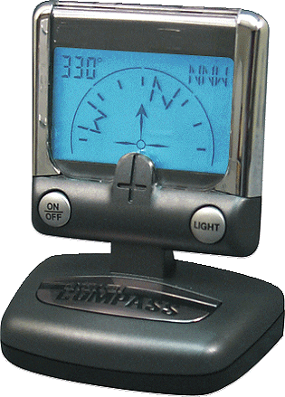
Electronic Compass Investigation
|
|
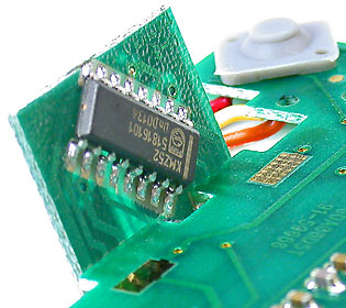 |
Left - The sensitive KMZ52 magnetic field sensor I.C. with two magnetoresistive thin-film permalloy Wheatstone bridges with integrated compensation and set/reset coils. The I.C. is on a small circuit board that's at an angle to the main circuit board so the I.C. will be nearly level when the compass is used in an auto with the display tilted at a typical viewing angle. I realized that a 2 axis compass depends on the I.C. being level with the earths surface for accuracy and that we would likely require a much more expensive 3 axis compass that uses a third sensor to eliminate the tilt problem, but I wanted to see just how critical it was to keep a 2 axis compass level which turned out to be very critical and make a compass like this totally useless for our application. |
|
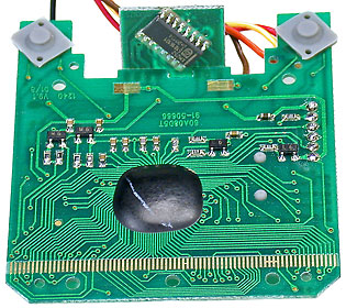 |
This is the front side of the main circuit board. The LCD display interfaces with the long multi-conductor strip along the bottom of the photo. The microprocessor chip that interprets data from the KMZ52 and functions as the LCD controller is embedded in the blob of black epoxy. |
|
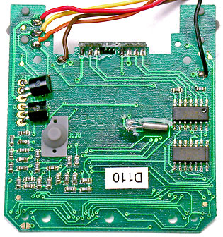 |
This is the back side of the main circuit board. The tiny silver cylinder with 2 leads is the microprocessor crystal. One of the two I.C.'s is a quad op-amp used to amplify the small output voltages from the KMZ52 circuit. |
|
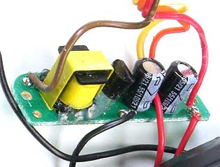 |
The compass is powered from four AAA cells using this small switching power supply. |
|
|
More details may follow if a use for an inexpensive 2 axis compass is ever found. |
||
|