
IRLP Node #1240 is on the
UHF VE6SBR Repeater - 444.800 MHz
A
103.5 Hz CTCSS access tone is required.
|
Edmonton IRLP & Internet Radio Linking Project
|
| Update - The VE6SBR repeater no longer exists but this page was left for the information and ideas it may provide. |
December 2000
Following are pictures of the link radio built to interface IRLP node 1240 to repeater VE6SBR.
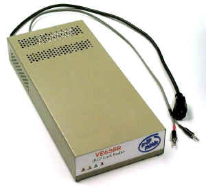 |
An ICOM U2 UHF handheld radio, a power supply and the IRLP DTMF tone decoder interface board were installed in an old computer back-up tape drive enclosure. |
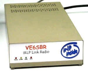 |
LEDs indicating DTMF Tone Detection, Receiver COS and Transmitter PTT were relocated from the IRLP interface board to the front panel beside the Power On LED. |
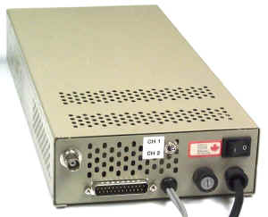 |
The enclosure rear panel has the radio BNC antenna connector, the radio channel selection switch, the 25 pin PC parallel port connector, the PC sound card interface cable, & the ON/OFF switch, fuse, & AC line cord. |
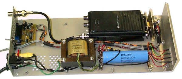 Enclosure Internal View |
|
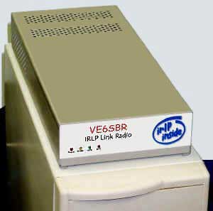 |
The link radio assembly on top of the IRLP computer. |
|
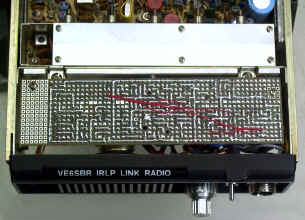
It was soon discovered that the "old" ICOM handheld had seen much better days and had numerous problems. Each time one problem was cured, two more seemed to develop and the radio would never be able to be counted upon to provide reliable service due to component and soldered connection failures resulting from old age and hard use. After countless hours of work, the radio was finally made acceptable for temporary service while a replacement radio was found and prepared. February 2001 - New WR-1454 Link Radio The link radio is at the home of James, VE6SRV, who provides the IRLP internet connection. He had a UHF antenna available for the link radio, but being antenna poor this left him having to use a VHF antenna on his UHF handheld to communicate with the VE6SBR repeater for IRLP conversations. The combination of the handheld's low power plus the less than ideal 3rd harmonic UHF match on the VHF antenna resulted in James having a less than full quieting signal into VE6SBR. It did not make sense for James to have to transmit his signal 12 miles just to access the IRLP link radio sitting several feet away from him so I designed the new link radio for dual purpose use. It provides both, the link radio function for IRLP and also functions as a standard radio for James to use for local VE6SBR repeater access. This is accomplished with some special audio path switching. To function as a standard IRLP link radio, the radio's receiver COS and transmitter PTT signals must be connected to the computers IRLP interface board. Also, the radio's input and output audio signals must be connected to the computers sound card. For James to also be able to use this radio as a standard radio, it has to be further modified so that - 1. When the IRLP node is active and James uses the radio to transmit to the repeater, the normal receiver audio fed to the computer must be replaced with the local mic audio and the receiver COS signal fed to the IRLP interface board must be replaced with the mic PTT signal so that the mic audio being transmitted to the repeater can also be sent to the IRLP system. 2. When the IRLP node is active and the radio is transmitting received IRLP audio to the repeater, the normal receiver audio to the radio's audio amplifier must be replaced with the received IRLP audio being feed to the radio's transmitter. In addition, the receiver COS signal that un-mutes the radio's audio amplifier must be replaced by the IRLP interface board PTT signal that keys the radio's transmitter so that the received IRLP audio can be heard locally. The following photo shows the front of the modified radio spread open and the board wired into the radio that was constructed to provide the required COS, PTT and audio switching. For such a small board it is unbelievable how many interconnecting wires are required. The large gray conductors are the two 1/8" shielded wires to & from the sound card. The small gray conductors are the 1/8" miniature shielded wires used within the radio. Also on the board is a relay for radio channel 1 / channel 2 selection, CTCSS tone encode/decode circuitry and a DTMF decoder that eliminates the need for a separate IRLP controller board. |
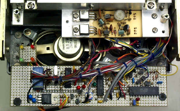 Link radio control board, wired into the radio, but before the radio is closed up. |
|
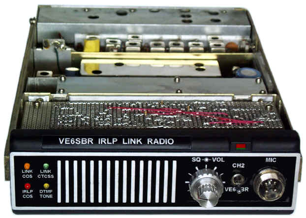
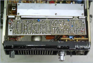 Original radio top view before removal of the tone access board. |
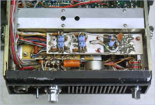 Original radio bottom view before removal of the 4 channel crystal oscillator board. |
 Modified radio top view showing bottom of the new IRLP control board. |
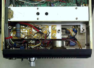 Modified radio bottom view |
 CLICK HERE for an animation of the radio in action. (1 MB) (Sorry, but the animation no longer works due to the way newer browsers work) (Hopefully I'll be able to find time before too long to fix this.) |
|
|
Using IRLP, you only hear the messages of the node accessed, never the node that you are on. For local users, the following buttons have been provided to play the node messages of |
||
| VE6SBR Node 1240 On Message | SARA Node 1260 On Message | |
| VE6SBR Node 1240 Off Message | SARA Node 1260 Off Message | |
|
||||||||||||||||||
| To VE6SBS Amateur Radio Home Page |