|
Additional Mic and Modification Information
The PDF files don't provide any real instructions as to how to perform the mod's other than what components to change or add as they are simply a PDF of my personal CAD drawings kept as a record of what I did in case I decide to make additional changes or get and modify
another mic, however I'm sure most won't have any trouble figuring out what needs to be done and how to do it.
Something that may require a bit of explanation is how to supply power to the mic's from the camera. Next to the camera audio input pin on connector 5 is a special audio input signal ground pin that's provided to keep the "noise" on the camera power supply ground from
affecting the audio signal. There's no problem when a mic is powered from a battery or a different power source than the one used to power the camera (like a separate wall wort that's only used to power the mic). But the mic only has a single ground connection for both, its supply
voltage and audio output signal which means, when the mic is powered from the cameras power source, that the 2 camera grounds will no longer be isolated and noise on the camera ground will affect the audio. Note: The audio will be affected by noise even if just the supply voltage
lead is connected to the mic (which would leave the 2 grounds unconnected) as the supply voltage ground noise is also present on the supply voltage and the noise will be coupled to the mic ground by the mic circuits supply voltage filter capacitor. The solution I came up with (and
that works perfect) is to use the supply voltage filter shown in the Mic Supply Voltage Filter PDF in conjunction with replacing the mic circuits diode with a 270Ω resistor and adding a second mic circuit filter
capacitor as shown in each of the Mic Modification PDF's.
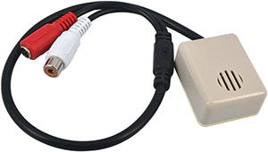
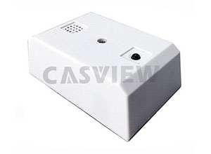
I selected the LY-901LS mic based on the sellers web page image showing it with a PCB with thru-hole components and a NE5532 dual op-amp IC, but the image is wrong and obviously an older model as the received mic's had PCB's with SMT components like all the others. No
big deal and actually better as it made the circuit board much smaller which I never planned on leaving inside the large enclosure the mic comes with and it was nice to see that the SMT IC identification markings hadn't been removed, like they had been on all the other mic's and
even though it wasn't a NE5532, as it's always nice to know what you're actually working with when modifying circuits. And disregard the listed freq. response spec as, like for all the mic's, this spec isn't even close to being correct and what's listed on the sheet with the mic,
even though it's quite different, is no better. (A simple freq. response spec., like 200Hz to 12KHz, can't actually be provided for the mic's with a gain control with how they are designed as the gain control affects the freq. response as well as the gain.)
One has to wonder where some of the spec's come from like the 12 to 60mA operating current spec provided for some of the mic's when the maximum current would never be more than 3 or 4 ma and it would never vary more than a mA for such mic's. Or the output level that's
often spec'd as 0 to 5 or 6Vp-p (which had me hoping that some mic's may be ok as is). 5 to 6Vp-p is pretty close to what the output level could be and the level at which clipping would occur if these mic's had much more gain, but the output would never be even close to that for
a mic with a gain of only ≈100. And don't believe any statements about a mic having a Noise Reduction Processing Circuit and/or Automatic Gain Control (AGC) as I've yet to find any that do and this is obviously simply an attempt to mislead buyers and increase sales.
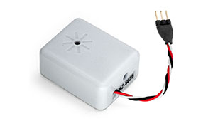
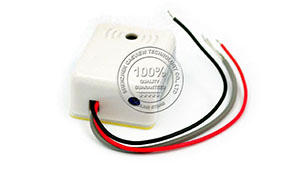
I began by modifying the two KZ-502B shown in the KZ-502B PDF. Different values were used for several components in the second circuit for a bit more gain and wider freq response to hear the difference this made, but it wasn't enough to bother changing and making the
first one the same (although I liked the second one a bit more for it's slightly higher gain). The mic element of circuit #2 was also separated from the circuit board using some 2 conductor shielded cable. Single conductor shielded cable would have likely worked as well for the
short distance, but for longer distances and where the cable will lay close to AC and other wiring which could introduce noise it's best to use 2 conductor shielded cable and I planned to use this second mic where the cable would be close to AC and switching power supply wiring
that often creates noise problems. As shown in the KZ-502B PDF, when using 2 conductor shielded cable the 2 conductors are used to connect the mic and the shield is only connected to the grounded mic conductor at the amplifier end.
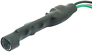
Wind Noise can be a big problem outdoors, but there's lot of info about it and how to solve the problem on the web and I've had great success using open-cell foam. Sponges and the foam used to package items is often open-cell which means there's a meandering path for
the air to move through it. This and a lot of other good information about curing wind noise was found on this web page which also says that the shape of the foam should be aerodynamic
(no sharp corners) to eliminate turbulence noise as the wind moves over it, but I've never paid much attention to the shape of the foam as close by the cameras I've added a mic to there's always been a place to put the mic that's fairly sheltered from the direct blast of the wind.
 To determine which pieces of open-cell foam may work best without affecting the sound I start by simply blowing through it and trying whichever are the easiest
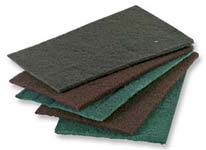
to blow through. The best so far has been some grey foam used to package items, but I just came across my box of sanding pads and discovered that they are very open and something I definitely plan to try using. To determine which pieces of open-cell foam may work best without affecting the sound I start by simply blowing through it and trying whichever are the easiest
to blow through. The best so far has been some grey foam used to package items, but I just came across my box of sanding pads and discovered that they are very open and something I definitely plan to try using.
Right - My assortment of sanding pads
Anyway, I hope this and my modification PDF pages help some add mic's to their cameras.
|