|
Update July 2015 - After working with a few different IPC boards, I've found trying to determine the model and what features a particular board has can be very frustrating. For the board described on
this page, the circuit board is labelled BLK18E-0012-38X38_S V1.01 and the cameras web page shows it has Firmware Version V4.02.R12.00006510.10010.1303. The "6510" in the firmware version is the Hardware ID and indicates the Product Model is IPC_HI3518E_50H10L_S38
within which there will be several different board models with different features and I was lucky this time and received a board with a sticker that identified it as a model 50H10PE-S which can be used to find what features the board has.
In case other firmware versions don't allow the alarm or audio I/O features described below to be used, here's the IPC_HI3518E_50H10L_S38_V4.02.R12.20150116_ALL.rar
that will install Firmware Version V4.02.R12.00006510.10010.1303.
Update Jan 2016 - This 50H10PE-S board is similar to the 53H13PE-S board on this page where the different features of 4 similar models are listed.
Update August 14, 2015 - Blue Iris update 4.1.4 resolved the alarm input issue mentioned near the bottom of this page and now that BI recognizes and will act on the alarm input I'll follow up with a page on how
the input was used with a passive IR/Microwave motion detector once I've finished doing that.
|
|
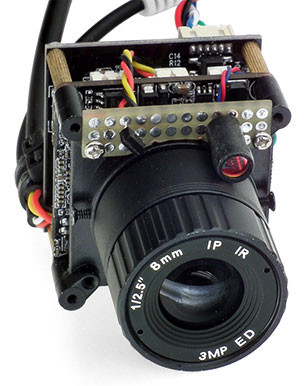
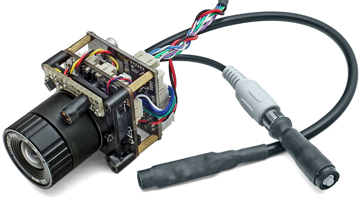
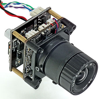
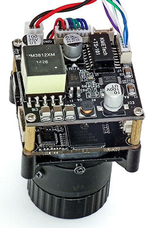
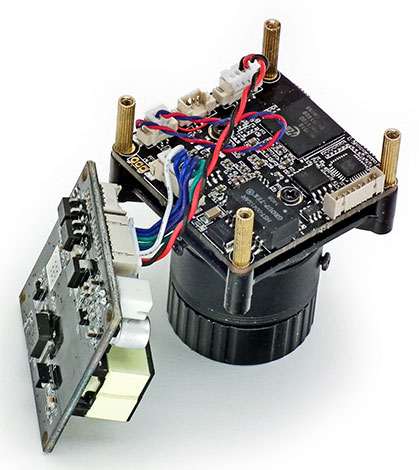
This is a 50H10PE-S board camera with a "C" mount lens that I've added a PoE board to like I've done with all my other cameras and as shown in this 50H10PE-S Mods.pdf.
(Disregard any reference to the camera IP in this PDF
as the PDF is simple a copy of my personal CAD file used to document the changes I've made to this particular camera and the IP is simply what's used for this camera on my LAN.)
The Review - TOP-201 Super Mini 720P HD IP-Cam (The Cheapest IP Cam So Far !!) thread on the IP Cam Talk forum has a lot
of info on the low cost board cameras like this from the Hangzhou Xiongmai Technology Co. that are being sold everywhere for as little as $20 and are perfect for those, like myself, that like to modify and add features to cameras and saves having to remove and discard the enclosure
from a more expensive camera when wanting to install a camera where space is limited. The thread has become quite long, but 2 of the most informative posts one should read are
Deep - Part 1 of 2 and
Deep - Part 2 of 2.
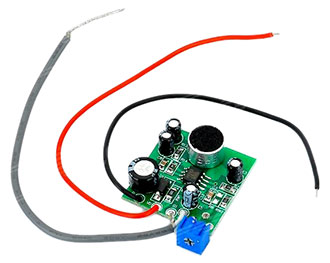
After finding the thread and info that my camera had an audio channel I decided to add a microphone. The audio input on all of my other cameras from various manufactures are for a mV (mic. level) signal from an electret mic. element, but the input on this and other cameras from
this manufacture is different and for a 2V (line level) signal from an amplified mic. I briefly considered making such a mic. using components I already had, but it simply wasn't worth it with what a smaller mic. than I could make cost and I simply bought the one seen below that
was only $2.50 with free shipping on eBay.
|
 |
|
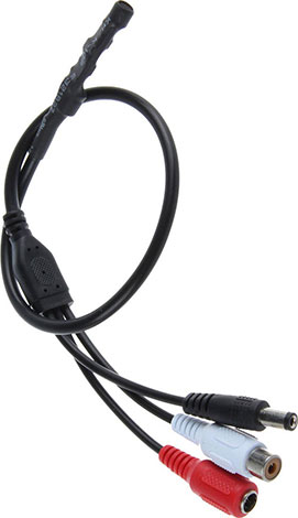 
 The connectors on the mic. weren't required, but provided 3 nice molded connectors on short cables for other projects after they were cut off next to the molded block where they split
off from the main cable. The molded block was also removed and a 1.25mm WTB connector 8 position plug was installed on the 3 wires from the mic. which plugs into the 8 position jack one needs to install on the camera board where space for one is provided. See this
50H10PE-S Board Camera Mods.pdf for wiring details and this eBay_Electret_Mic.pdf and this Modified_eBay_Electret_Mic.pdf for schematics and information on the stock
and modified mic. The connectors on the mic. weren't required, but provided 3 nice molded connectors on short cables for other projects after they were cut off next to the molded block where they split
off from the main cable. The molded block was also removed and a 1.25mm WTB connector 8 position plug was installed on the 3 wires from the mic. which plugs into the 8 position jack one needs to install on the camera board where space for one is provided. See this
50H10PE-S Board Camera Mods.pdf for wiring details and this eBay_Electret_Mic.pdf and this Modified_eBay_Electret_Mic.pdf for schematics and information on the stock
and modified mic.
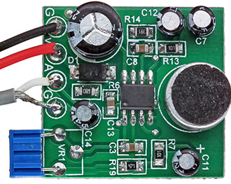
Adding the mic. wasn't as simple as simply connecting it to the camera however, and the mic. also required a couple of modifications. The mic. amplifier gain was only 80 and not enough to provide a proper signal level for this camera, so the 220Ω gain setting resistor Rg was
changed to a 0Ω for the maximum gain of 200 which helped a lot, but I would have preferred a bit more. Another issue is that the 5V supplied by the camera is actually only ≈ 4.85V and the mic. requires at least 4.45V to operate. While the mic. did work with 4.85V, it left little
margin if the supply voltage dropped or the min. mic. voltage required increased at higher or lower operating temperatures so I decided it would be best to remove the diode which I figured was simply for reverse voltage protection, but removing the diode introduced a lot
of audio noise from what little noise was on the supply voltage. It's hard to say if the diode was for reverse voltage protection, noise filtering or perhaps both, but after hearing the noise I realized that it could actually be heard, although barely, when the diode was used and
decided to find a better solution which was to replace the diode with a resistor. A 10Ω resistor worked pretty good, with 15Ω the noise could just barely be heard and in the end I decided to use a 100Ω resistor that eliminated the noise completely and only dropped the supply voltage
≈ .4V or about half what the diode did.
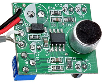
This mic. is a bit larger and cost a bit more than the first one ($5.21 with free shipping), but works perfectly without any modification and the next ones will even be a bit less ($4.62 each) as I plan to buy at least 3 more now that I know how well
they work. Unlike the first one, this mic. has plenty of gain and provides an audio signal that's almost 6Vp-p before it becomes distorted when the mic. is operated on 12VDC. I used to be happy with what my other cameras that came with a mic. heard outdoors, but with the gain control
of this mic. set to maximum it clearly hears things the others just barely hear, or don't hear at all, and often picks up sounds from blocks away. Like the first mic., I also reverse engineered this one and created a schematic that can be found in this
DX_Electret_Mic.pdf along with other information.
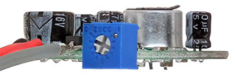 |
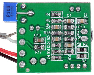
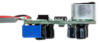
Although the mic. works perfectly ok without any modification, some modification is needed due to the cap's being as tall as the mic. element when wanting to install the mic. element in a panel hole as is often done. It appears that moving the
mic. element to the bottom side of the PCB would solve the problem and that the adjustment pot could be moved from the edge to the top side of the board to make it easier to adjust in cases like this where the PCB is mounted close to a panel. Left - side view before
the board was modified. |
|
However the mic. element pins are offset, rather than centered like those of a cap, and this would end up making the element polarity wrong if moved to the other side of the PCB.
And moving the control pot to the top side of the board would also end up making its operation backwards, i.e. CW rotation would decrease, rather than increase, the gain and vice versa.
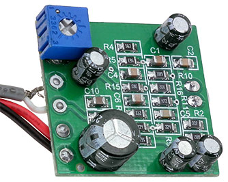
But, rather than move the mic., it's just as easy to move the 5 large cap's to the bottom of the board and if the control pot is also moved to the bottom its operation won't become reversed.
|
 |
 |
|
Above Left - Modified Board Top Side,
Above Right - Modified Board Bottom Side
and Right - Modified Board Side View.
|
 |
|